Monday, April 20, 2020

Analysis of trusses by joint and section method


Numerical problem on the truss Analysis by method of joints

Analyse the given truss given below by using the method of joints


Step 1: Converting the supports into reactions as shown in figure below
Step 2: Check for Determinacy
                           w.k.t.

                          m+r-2j=0
                           
                           
                           9+3-2(6) =0
                         
                           Therefore, the structure is determinate.
                           
                            Where, 

                            m = The number of members in the structure
           
                            r =   Support Reactions
             
                            j =   Number of joints


Step 3: Calculation of support reactions
               
               Number of unknown reactions = 3 (.i.e. HA, VA & VD)

               Applying the equilibrium conditions

               ΣH = 0

                HA + 80 = 0 ……….. (1)

                Therefore, HA = -80 KN

                ΣV = 0

                VA + VD = 50KN.............. (2)

               Taking moment about support D

               VA (3) – 50 (1) + 80 (0.75) = 0............. (3)

               Solving the above equation

               VA = - 3.33KN

               Substitute VA in Eq (2)

               Therefore, VD = 53.33 KN

 Step 4: Free body diagram representing the nature of forces


Step 5: Solving joint A


Applying horizontal equilibrium condition

ΣH = 0

-80 + FAE + FAB Cosϴ = 0

(ϴ = Tan-1(0.75/1))

(ϴ = 36.86o)

FAE + FAB Cos36.86 = 80……… (1)

ΣV = 0

-3.33 + FAB Sinϴ = 0

FAB Sin36.86 = 3.33

Therefore, FAB = 5.55 KN (Tensile)…… (2)

Substitute (2) in (1)

FAE = 75.56KN(Tensile)

Step 6: Solving joint B

Applying horizontal equilibrium condition

ΣH = 0

FBC - FAB Sinα = 0

FBC – 5.55Sin 53.13 = 0

FBC = 4.44 KN

ΣV = 0

-FBE – FAB Cosα = 0

-FBE – 5.55Cos 53.13 = 0

 FBE = -3.33KN

FBE = 3.33KN (Compression)

Step 7: Solving for joint E

ΣH = 0

- FAE + FEF + FEC Cosϴ = 0…… (1)

ΣV = 0

-FBE + FEC Sinϴ = 0

-3.33 + FEC Sin 36.86 = 0

FEC = 5.55KN (Tensile) ………. (2)

Substitute (2) in (1)

- FAE + FEF + FEC Cosϴ = 0

-75.56+ FEF +5.55Cos 36.86 = 0

Therefore, FEF = 71.12KN(Tensile)

Step 8: Solving for joint F


          ΣH = 0
          
          FEF = FFD
        
          FFD = 71.12KN (Tensile)
          
          ΣV = 0
          
          FFC = 50KN (Tensile)

Step 9: Solving for joint C


          ΣH = 0

         -FBCSinα +80 + FDC Sinα = 0

         -4.44Sin53.14 + 80 + FDC Sin53.14 = 0

          FDC = - 95.55KN

          FDC = 95.55KN (Compression)

                   Numerical problem on the truss Analysis by method of Sections

                      Determine the forces in the members BD , CD & CE

Step 1: Sectioning of a truss


Step 2: Check for Determinacy
          w.k.t.

    m+r-2j=0

. i.e., 7+3-2(5) =0
                                
Therefore, the structure is determinate.

Where, 

m = The number of members in the structure
           
 r =   Support Reactions
             
j =   Number of joints

Step 3: Determination of support reactions

Applying the equilibrium conditions

ΣH = 0

Therefore, HE = 0……… (1)

ΣV = 0

VA + VE = 8000 N…….. (2)

Taking moments about E

VA (2) + 4000 (1) – 1000 (1.5) – 3000(0.5) = 0

Therefore, VA = 3500N

Substitute (2) in (1)

VE = 4500N

Step 4: Determination of unknown forces


Taking moment about C

-VE (1) + 3000(0.5) – FDB (0.866) = 0

Solving the above equation,

FDB = -3464 N

FDB = 3464 N (Compressive)

Applying vertical equilibrium condition

ΣV = 0

-3000 - FDCSin60 + VE = 0

Therefore, FDC = 1732.05N (Tensile)

Taking Moments about D

-VE (0.5) +FCE (0.866) = 0

FCE = 2598N


CONDITIONS OF EQUILIBRIUM


CONDITIONS OF EQUILIBRIUM


The structure is said to be in equilibrium if algebraic sum of all forces and moments are balanced.

It can also be explained as the magnitude of force acting on the structure is resisted by another force or set of forces of equal in magnitude and opposite in direction to the load acted.

Therefore, it can be stated that the net resultant force on the structure is equal to zero.
               Fig 1                                                                           Fig 2


                                                               Fig 3


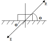
·        Consider the figure 1 in which the body on the rigid support is subjected to the external forces of magnitude F1, F2, F3 and F4.

·   Further all forces are brought into a single force (Resultant –R); whose effect is same as that of combined effect of all the individual forces (shown in fig 2).

·    In order to maintain the body in the equilibrium state, the same magnitude of the force but opposite to the direction of the resultant will be acted on the body which is termed as equilibriant (E) (shown in fig 3).
 

Generally there are three conditions of equilibrium


1.     The algebraic sum of all the forces in horizontal direction or x direction acting on a structure is equal to zero.

∑F x = 0

2.     The algebraic sum of all the forces in horizontal direction or x direction    acting on a structure is equal to zero.

∑F y = 0


3.     The algebraic sum of all the moments acting on a structure is equal to zero.
      ∑M = 0


First two conditions are called as force equilibrium or translational equilibrium. The last condition is also called as torque equilibrium or rotational equilibrium.

Example for force equilibrium:
·        A book resting on the table.
·        A car moving with constant velocity
            
            Example for torque equilibrium
·        Children playing See saw
·        Driving Car steering


Sunday, April 19, 2020

LOAD TRANSFER MECHANISM IN A STRUCATURAL SYSTEM


LOAD TRANSFER MECHANISM IN A STRUCATURAL SYSTEM
The process of transfer of exposed load from one structural element to the other structural element is called as load transfer mechanism. Load transfer mechanism basically depends on the elements on which load transfers, this is referred to as load path. Based on the load path the pattern of load transfer mechanism varies which in turn depend on the type of load which the structure has to transfer.

Generally there are two types of load paths they are
1.     Gravity load path
2.     Lateral load path

Gravity load path: In this type of load path the vertical gravity load; which includes the dead load of the structure and live load on the structure acts on the slab are efficiently transferred to beams, from beams it is then transferred to columns and from columns to the supports, finally from the supports to the underlying earth.

The load transfer mechanism of gravity load path is generally shown by the figure below

                             
        Pattern of load transfer in gravity load path
1.     In case of transfer of the load from slab to the adjacent beams the triangular or trapezoidal pattern is followed, which in turn causes additional torsional moment on the beam at its ends.

2.     The loads received by the slabs on the beams at the joints will causes in bending of the beam and the results to form 3 reactions at its end position  

·        One in vertical direction - Acts as an axial load on the neighboring column.
·        One in horizontal direction – Acts as a shear force on the neighboring column.
·      Moment at the end of the beam - Acts as a bending moment on the neighboring column.

3.     The loads on the columns transfer to the supports efficiently and further to the foundation soil. The structure can be said to be stable if the upward pressure by the foundation soil is equally resisted by the load on the structure.

Lateral load pattern: In this type of load path the lateral loads; which are the earthquake loads and wind loads are transferred efficiently through the building. The components of the lateral load paths are

a.     Horizontal components such as roof, floor and foundation.

b.     Vertical components such as shear wall and frames.


Pattern of load transfer in Lateral load path
1.     Roofs and floors which are also called as diaphragms; transfers load to the shear walls(also termed as the primary load resisting elements).
2.     Shear walls can also resist the gravity loads efficiently and further transfers the collective load to the foundation; inturn foundation collects loads from all the stories and then transfers it into the underlying soil.


Friday, April 17, 2020

Analysis of structure


Analysis of structure

Based on the forces for analysis, structures are classified into two types

1.     Determinate structures
2.     Indeterminate structures

Determinate Structures: The structures whose unknown forces can be determined by using the equilibrium conditions itself are called as determinate structures.


Indeterminate Structures: These are the structures in which the unknown forces cannot be analyzed by using conditions of equilibrium only but instead it requires the additional equations to determine the unknowns which are called as compatibility equations.

Degree of indeterminacy
Degree of Indeterminacy is nothing but the number of redundants that has to be calculated .DOI is classified into two categories such as

1.     Statically indeterminate structure
2.     Kinematically indeterminate structure

Statically indeterminate structure: It is the number of additional equations required apart from equilibrium conditions to solve the unknown reactions of the structure.

Static Indeterminancy is further classified into two categories
·        External Static Indeterminancy
·        Internal Static Indeterminancy

External Static Indeterminancy: It is the type of static Indeterminancy, caused due to the unknown reactions of the support itself.

De = R-3 (for 2D structures)
De =R-6 (for 3D structures, since for 3D structures, there will be 6 equilibrium conditions)

Where De = External Static Indeterminacy
R= Number of Support Reactions
                       
                       De=R-3 = Externally Determinate Structure
                       De> R-3= Redundant structure
De< R-3=Unstable structure

Internal Static Indeterminancy: It refers to geometrical stability of the structure.If the internal forces of the members cannot be determined by equilibrium conditions itself then it is said to be internally indeterminate.
For geometric stability of structures sufficient members are requires to preserve the shape of the structure without causing excessive deformation.

Dsi =3C-Rr            (Where C= No of closed loops
Dsi =6C-Rr                                Rr= Released reactions)

Therefore Static Indeterminancy= External + internal Indeterminancy

Degree of static Indeterminancy for different structures.
  1. Plane Frame = 3m+r-3j
  2. Space Frame = 6m+r-6j
  3. Plane Truss = m+ r-3j
  4. Space Truss = m+r-2j
Kinematic Indeterminancy

It is the number of free displacement of the structure which are unknown in addition to the compatibility equations.

Hence the extra equations required to determine the additional unknown displacements are called as kinematic Indeterminancy or it is also called as degree of freedom.

Thursday, April 16, 2020

DEGREE OF FREEDOM


DEGREE OF FREEDOM

Degree of freedom (DOF) is defined as the set of independent displacements/rotations that describe the deformed shape of the structure with respect to its initial position.

In simple terms, DOF of the structure is the number of directions the structure can be moved freely without any restrainment.

As in case of two dimensional structures; each joint will have the 3 possible degrees of freedom .i.e., one in horizontal direction, one in vertical direction and one rotation. But as in case of 3 dimensional structure; each joint will have the 6 possible degrees of freedom .i.e., 2 in horizontal direction ,2  in vertical direction and 2 rotation.

Mode number and mode type are the two important factors on which dof depend. Since every possible mode has to fit with the respective moving direction of the structural element. Therefore structure with more dof has more complicated modes.

Example: The train moving freely on the rail. This means the train can move freely along the rail in only one direction itself. Therefore the DOF for the above case will be 1.

Human head has 6 degrees of freedom

DOF is calculated as

DOF=R-S

Where R= 3, .i.e, Conditions of Equilibrium

S= No of Reaction forces of the support which required to resist the External load acting.

Degree of freedom for various support conditions

For Simple support
R = 3 ; S = 1 (i.e vertical direction)
Therefore, Dof = 2 (1 Horizontal direction and 1 rotation)

For Hinged support
R = 3 ; S = 2 (i.e vertical direction and 1 Horizontal direction)
Therefore, Dof = 1 (  1 rotation)

For Roller support
R = 3 ; S = 1 (i.eVertical direction)
Therefore, Dof = 2 (1 Horizontal direction and 1 rotation)

For Fixed support
R = 3 ; S = 3 (i.e Vertical direction , 1 Horizontal direction and 1 rotation)
Therefore, Dof = 0

Tuesday, April 14, 2020

Structure and structural forms

Structure and Structural forms

Structure is the assembly of the elements interconnected with each other which is exposed to the external loading and transfers the same load coming on it through its elements to the under-laying system.

Therefore, Structure is the one which is exposed to the external loading and transfers the load coming on it through its neighboring elements to the under-laying system.

Structural Analysis is the study of determination of the effects of the loads on the structure and its components.

The elements of the structure through which the loads are transferred to the under laying system  are called as structural forms.

Generally structural forms are classified into 3 groups:
      One dimensional element: These are the elements on which the load is applied along the length and the corresponding deformations will takes place in the same direction as that of the applied load. Generally, in this type of element; the length of the element is greater than the other two dimensions.
Example: Beams, Cables etc.…

      Two-dimensional element: These are the elements on which the loads are applied along both length and width and the corresponding deformations will takes place in both X and y directions of the element corresponding to the load applied. The thickness of the element is smaller than other dimensions as in case of two-dimensional elements.
          Example: Plates, Shells etc.…


  •  Three-dimensional element: These are the elements on which the loads are applied along all the 3 dimensions and the corresponding deformations will takes place in all X ,Y and Z directions of the element corresponding to the load applied.

        Example: 3D solids

Monday, February 24, 2020

Theory of failure - Rankine's theory

Rankine's Theory or Maximum Principal stress theory

     According to this theory, Failure of the structure takes place when the major principal tensile stress reaches the value beyond elastic limit in simple tension and minor principal stress(compressive in nature) reaches a value beyond elastic limit in simple compression.

Consider the three dimensional structure subjected to stresses in three mutually perpendicular directions, let σ1 , σ2 and σ3 be the normal stress in all 3 respective directions in which , σ1 and σ2(Major principal stress) be the normal stress in tensile nature and σ3 (Minor principal stress) normal stress  which is  compressive in  nature.Therefore, According to this theory, the failure of the material takes place as follows
  • σ1 and σ2 ≥ σt in simple tension.
  • σ3  ≥ σc in simple compression
Therefor if the material has to be safe against failure, then the maximum principle stress should not exceed permissible stress.
  • σ1 and σ2 = σp
  • Since,  σp = σt / FOS
where  σp = permissible stress , σt = Tensile stress after elastic limit
Limitation of Rankine's theory
  • This theory is only applicable for structure made of brittle materials subjected to all loading conditions.Since brittle materials are weak in tension.
  • This theory is not suited for structures made of ductile material, since the ductile material is weak in shear.But only in some conditions the theory holds good for ductile materials .Some of the conditions are as follows
  1. Under uni axial state of stress when maximum shear stress is equal to half of maximum principal stress.
  2. Under bi axial state of stress when there is occurrence of like forces and also when maximum shear stress is equal to half of maximum principal stress.
  3. Under hydrostatic condition .i.e, when shear stress at all the boundaries is equal to zero.

Sunday, February 23, 2020

THEORY OF FAILURES - Introduction

THEORIES OF FAILURE 


     When a structural element has to be designed,then it is important to determine its strength and stability based on the elasticity,yielding and fracture.As a element alone , it is easy to determine its structural behavior in terms of simple stress and strain.But in reality, the structure cannot be analysed as a part since , load applied and its corresponding stress and strain behavior will be in complex form.Some of the theories were designed to predict failure pattern for simple loads were also declared to be feasible for complex loading also.But these theories used to predict failure pattern in complex loading , failed to provide proper results in practical conditions, hence they are termed as theories of failure.The following are the five theories of failure put forth by researchers.

  1. Rankine's theory or Maximum Principal Stress theory.
  2. Columb's theory or Maximum Shear stress theory.
  3. St Venant's theory or Maximum Strain theory.
  4. Beltrami and Haigh's theory or Maximum strain energy theory.
  5. Von-Mises theory or Maximum Energy distortion theory.