Tuesday, July 3, 2018

Difference between dry process and wet process of cement production.


Difference between dry process and wet process of cement production.


Dry process
Wet process
Raw materials are mixed in its dry state
Raw materials are mixed in wash mill along with 30-50% of water
Dry mixed raw materials entering to the kiln are called as kiln feed
Wet mixed raw materials entering to the kiln is called as slurry
Size of kiln required in this process is less
Size of kiln required in this process is more
Since the mix is in dry state, therefore achievement of homogeneity of the mix is of lesser degree
Raw materials are mixed in wet state , degree of homogeneity of the mix achieved is high
Fuel consumption for this process is less
Fuel consumption for this process is more
Energy required is less
Energy required is more
Cost of production is less
Cost of production is more
Carbon di oxide emission is comparitively less in this process
Carbon di oxide emission is comparitively more in this process

Monday, July 2, 2018

CEMENT AND ITS MANUFACTURING PROCESS


Cement Introduction: Cement is the world’s second largest consumed product next to water. It is a fine powdery, inorganic, hydrophilic material which forms a paste, sets and hardens due to hydraulic reaction when mixed with water. Cement is the important binding material which adheres to the other materials of construction and there by results in homogeneity of the resultant product.
Currently, India is second largest producer and consumer of cement after China. However, China’s production is nearly nine times higher than India.
Manufacturing process of cement

Manufacturing process of the cement involves the following stages

1     Stage 1:

Collection of raw materials: Raw materials, which are of mineralogical origin or industrial waste products can be used for cement production. Major components used for cement production are of calcareous and argillaceous materials. Calcareous materials are those containing maximum part of calcium based compounds in its composition. Whereas argillaceous materials are those containing fine grained alumina (clay) minerals in its composition. Some of the calcareous and argillaceous based rocks which are commonly used for cement production are listed in table 1 below

Table 1: list of Calcareous and argillaceous materials

Calcareous materials
Argillaceous materials

Silicon based
Aluminum based
Iron based
Limestone
Sand stone
Fly ash
Blast furnace slag
Marl
Fly ash
Aluminum ore refuse
Iron ore
Calcite
Rick husk Ash

Shale
Aragonite
Slag


Shale


Sea shell


Stage 2:

Grinding, Mixing and proportioning of the raw materials: The collected raw materials are crushed into small sizes and then stored in large tanks. Further, the raw materials are mixed and proportioned before feeding it into the rotary kiln. In order to obtain good quality of cement, the raw materials should be mixed and fed proportionately. The quantity of raw materials feeding into the kiln depends on the purity of the material. Generally, if the material is pure to its maximum extent, then lime stone is fed 80% and clay is taken as 20% of the total weight of raw material.


 Stage 3:  

Pre heating of the raw material: After final grinding, the material is ready to face the pre-heating chamber. Pre-heater chamber consists of series of vertical cyclone from where the raw material passes before facing the kiln. Pre-heating chamber utilizes the emitting hot gases from kiln. Pre-heating of the material saves the energy and make plant environmental friendly.


Stage 4:

Burning phase: In this phase the preheated raw materials are burned up to 1500oC in the huge rotating furnace called as kiln. At this temperature limestone releases huge amount of carbon di oxide, and the process is called decarbonation. Further due to the exposure of high temperature there will be series of chemical reaction between limestone (calcium carbonate) and clay (silicon di oxide) compounds to form primary constituents of cement. When the material reaches lower part of the kiln, it forms clinkers.

Stage 5:

Cooling and final grinding: The clinkers are finally cooled by lowering the temperature by means of forced air. After cooling the clinker, it is then passed to the horizontal rotating drum, filled with steel balls. Here, steel balls tumble and crush the clinker into a very fine powder. During grinding gypsum is also added to the mix in small percentage that controls the setting of cement.

Stage 6:

Packing
Material is directly conveyed to the silos (silos are the large storage tanks of cement) from the grinding mills. Further, it is packed to about 50 kg bags. Only a small percent of cement is packed in the bags only for those customers whom need is very small. 

Tuesday, January 16, 2018

Limitations of Euler's theory

The general expression of bucking load for the long column as per Euler’s theory is given as,
P = Π 2E I / L2
σ = Π 2E / (Le / k) 2
We know that, Le / k = slenderness ratio
Limitation 1: The above formula is applied only for long columns
Limitation 2: As the slenderness ratio decreases the crippling stress increases. Consequently if the slenderness ratio reaches to zero, then the crippling stress reaches infinity, practically which is not possible.
Limitation 3 : if the slenderness ratio is less than certain limit, then crippling stress is greater than crushing stress ,which is not possible practically. Therefore, up to limiting extent Euler’s formula is applicable with crippling stress equal to crushing stress.

Friday, January 12, 2018

Euler's theory assumptions for long columns

Some of the assumptions of Euler's theory for long columns are
  1. The geometric and material properties of the column is uniform throughout the section,i.e, flexural rigidity is constant all through.
  2. The material is isotropic homogeneous and elastic.
  3. The layers of the columns are assumed to be straight before the application of the load.
  4. The load on the column is usually applied axially at its ends.
  5. Since the slenderness ratio  for the long column is more ,it fails by buckling only.
  6. Self weight of the column is neglected during the calculation of failure load on the column.
  7. The linear dimension of the long column is much more compared to the lateral dimension.
  8. Long column experiences bending stress at a higher extent than compared to the direct stress.

Basic Properties of Materials

Density: It is defined as mass per unit volume.  It is expressed as kg/m3.

Specific gravity: It is the ratio of density of a material to density of water.

Porosity: The term porosity is used to indicate the degree by which the volume of a material is occupied by pores.  It is expressed as a ratio of volume of pores to that of the specimen.

Strength: Strength of a material has been defined as its ability to resist the action of an external force without breaking.

Elasticity: It is the property of a material which enables it to regain its original shape and size after the removal of external load.

Plasticity: It is the property of the material which enables the formation of permanent deformation.

Hardness: It is the property of the material which enables it to resist abrasion, indentation, machining and scratching.

Ductility: It is the property of a material which enables it to be drawn out or elongated to an appreciable extent before rupture occurs.

Brittleness: It is the property of a material, which is opposite to ductility. Material, having very little property of deformation, either elastic or plastic is called Brittle.

Creep: It is the property of the material which enables it under constant load to deform slowly but progressively over a certain period.

Stiffness: It is the property of a material which enables it to resist deformation.

Fatigue: The term fatigue is generally referred to the effect of cyclically repeated stress. A material has a tendency to fail at lesser stress level when subjected to repeated loading.

Impact strength: The impact strength of a material is the quantity of work required to cause its failure per its unit volume.  It thus indicates the toughness of a material.

Toughness: It is the property of a material which enables it to be twisted, bent or stretched under a high stress before rupture.

Thermal Conductivity: It is the property of a material which allows conduction of heat through its body.  It is defined as the amount of heat in kilo calories that will flow through unit area of the material with unit thickness in unit time when difference of temperature on its faces is also unity.

Corrosion  Resistance: It is the property of a material to withstand the action of acids, alkalis gases etc., which tend to corrode (or oxidize).

Thursday, January 11, 2018

Stress-Strain diagrams for ferrous and non-ferrous materials

Relationship between Stress and Strain are derived on the basis of the elastic behaviour of material bodies.

A standard mild steel specimen( ductile specimen) is subjected to a gradually increasing pull by Universal Testing Machine. 


The stress-strain curve obtained is as shown below.
Stress strain diagram for ductile material

A -Elastic Limit
B - Upper Yield Stress
C - Lower Yield Stress
D -Ultimate Stress
E -Breaking Stress

Point A : Elastic limit point or Proportionality point: Proportional limit is point on the curve up to which the value of stress and strain remains proportional. The stress up to this point can be also be known as proportional limit stress.Hooke’s law is obeyed between the point O to A.

Point B : Upper Yield point:  Yield strength or yield point is the material property defined as the stress at which a material begins to deform plastically.Upper yield point is the point wherein the   stress increases and correspondingly strain also increases.

Point C : Lower Yield point : It is the point where the load remains constant and strain is increased correspondingly.

Point D : Ultimate Stress Point/ Maximum Stress point: Ultimate stress point is the maximum strength that material have to bear stress before breaking. It can also be defined as the ultimate stress corresponding to the peak point on the stress strain graph. 

Point E : Breaking point /Failure point/ Fracture point : Breaking point or breaking stress is point where strength of material breaks.  The stress associates with this point  known as breaking strength or rupture strength.

Stress strain diagram for Brittle material

Point A : Elastic limit point or Proportionality point: Proportional limit is point on the curve up to which the value of stress and strain remains proportional. The stress up to this point can be also be known as proportional limit stress.Hooke’s law is obeyed between the point O to A.

Point B : Breaking point /Failure point/ Fracture point : Breaking point or breaking stress is point where strength of material breaks.  The stress associates with this point  known as breaking strength or rupture strength. 

Section Modulus


                                            Section modulus

The moment carrying capacity of an object is directly dependent on geometrical property (I) and material property (E) of an object,which is collectively termed as flexural rigidity(EI).Geometry of an object plays an important role in load bearing capacity of an object which is indicated by moment of inertia of a section. Therefore section modulus is the predominant factor which evidences the strength of an object and is defined as the ratio of the moment of inertia of the object about its centroidal axis to the distance of the extreme fibers of the object from the neutral axis.


Section modulus is generally denoted by Z.
Therefore ,  Z = I / Ymax 
where, I = Moment of inertia of a section.
          Ymax = Distance of the outer most fiber of the object from the neutral axis.


Section modulus can also be defined by using the simple bending theory as,
we know that, M / I = σ / Y
Therefore, Z = M / σ 
i.e, section modulus is also expressed as the ratio of bending moment to the bending stress of a given object within the elastic limit.


Significance of section modulus
  1. Section modulus is the important factor for design of beam and flexural member
  2. Higher the value of section modulus, higher will be the resistance of member to bending
  3. It is required to calculate stresses in beams.
  4. It is used to calculate strength of the steel structure
  5. More the section modulus, it can withstand more load and it is also considered to be more tougher.

Saturday, December 30, 2017

Equilibrium of Forces


Whenever a body (static or dynamic) is subjected to external force then it tends to remain in the same state as it was in the former case, so that the algebraic sum of horizontal , vertical forces and moments is equal to zero as a result the condition is termed to be in equilibrium.

Conditions of Equilibrium,

1) The algebraic sum of all the horizontal forces or forces in X direction is equal to zero .i.e, ΣH=0 or ΣX=0


2) The algebraic sum of all the vertical  forces or forces in Y direction is equal to zero .i.e, ΣV=0 or ΣY=0


3) The algebraic sum of all the moments for the system  is equal to zero .i.e, ΣM=0

Note:
ΣH or ΣV = 0 and ΣMx=0 or ΣMy=0 (In case of one dimensional system)
ΣH , ΣV = 0 and ΣMx=0 , ΣMy=0 (In case of two dimensional system)
ΣH , ΣV, ΣZ = 0 and ΣMx=0 , ΣMy=0 ,ΣMz=0(In case of three dimensional system)

Thursday, December 21, 2017

Pure Bending

PURE BENDING

FIGURE  1

FIGURE  2

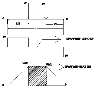
whenever the structure is applied with some magnitude of load, then there is a resultant of shear force and a couple simultaneously.consider the above figures we can observe that some part of the beam is 
resulted to negligible or zero shear force but at the same part of the structure, the bending moment is maximum or constant.Therefore, pure bending  is the condition of stress where the bending moment is maximum or constant  simultaneously the shear force or the torsional force is zero or negligible.

Friday, December 30, 2016

PROBLEMS ON VOLUMETRIC STRAIN,LATERAL STRAIN,LONGITUDINAL STRAIN AND POISSON’S RATIO


      1)    Determine the changes in length, width and thickness of a steel bar which is 4m long, 30 mm wide and 20mm thick and is subjected to an axial pull 30KN in the direction of length. E=2x10⁵N/mm2 and poison’s ratio=0.3.Also determine the volumetric strain, change in volume and final volume.
      
            Step 1: Data
          Length: 4m = 4000 mm
            Width = 30mm
Thickness = 20mm
Load = 30KN
E=2x10⁵N/mm2
poison’s ratio= 0.3
volumetric strain, change in volume and final volume = ??

Step 2: Calculation of area of the material
A= b X d
A = 30 X 20
A = 600mm2

Step 3: Calculation of stress:
Stress = Load/area of cross section
Stress = 30 X 1000 /600
Stress= 50 N/mm2

Step 4: Calculation of longitudinal strain:
E = σ/e
2x105 = 50/e
Longitudinal strain = 0.25X10⁻³

Step 5: Calculation of lateral strain:
ϻ = lateral strain/ longitudinal strain
0.3 = lateral strain / 0.25X10⁻³ 
lateral strain = 0.075X10⁻³ 

Step 6: Calculation of change in volume
ev = (dl/l)(1-2ϻ)
ev=(0.25X10⁻³)(1-2(0.3))
ev= 0.1X10⁻³    

Step 7 Calculation of change in volume:
ev = dv/v
Volume = lbd
             = (4000) (30) (20)
             = 24x105 mm3
0.1X10-3 = dv/24x105 
dv= 240 mm3

VOLUMETRIC STRAIN

Volumetric strain: Volumetric strain of a deformed body is defined as the ratio of the change in volume of the body to the deformation to its original volume. If V is the original volum and dV the change in volume occurred due to the deformation, the volumetric strain ev induced is given by

                                                                      
  ev=dV/V 


Consider a uniform rectangular bar of length l, breadth b and depth d as shown in figure. Its volume V is given by,

This means that volumetric strain of a deformed body is the sum of the linear strains in three mutually perpendicular directions.


LATERAL STRAIN,LONGITUDINAL STRAIN AND POISSON'S RATIO

Longitudinal strain : Whenever the bar is subjected to the axial load ,there will be increase in the length of the bar along the direction of loading. Therefore the longitudinal strain is defined as ratio of increase in the length of the bar in the direction of applied load to that of the original length (gauge length).

i.e, e = dL/L
where
e= longitudinal strain
dl= increase in length
L = gauge or original length


Lateral strain: Whenever the bar is subjected to the axial load ,there will be decrease in the dimensions of the bar in the perpendicular direction of loading. Therefore lateral strain is defined as ratio of decrease in the length of the bar in the perpendicular direction of applied load to that of the original length (gauge length).
i.e, e = dB/B or dD/D

where
e= lateral strain
dd= decrease in depth
D= gauge or original depth
db= decrease in breadth
B = gauge or original breadth

Poisson’s ratio:  The ratio of lateral strain to that of the longitudinal strain is termed as poisson’s ratio and it is represented by ϻ or 1/m.

i.e, ϻ or 1/m =  lateral strain/longitudinal strain

Value of the Poisson’s ratio for most materials lies between 0.25 and 0.33.