SLOPE AND DEFLECTION FOR A CANTILEVER BEAM SUBJECTED
TO EXTERNAL MOMENT
Fig 1
Fig 2
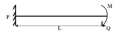
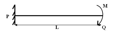
Consider a cantilever beam PQ of length L subjected to external moment M
on the free end side of the beam.
Fig
2 show the M/EI diagram for the beam subjected to external moment. The effect
of moment remains same throughout the beam; hence there is invariability in
M/EI diagram.
Slope
at the free end = Area of M/EI diagram
ϴQ = (L) (-M/ EI)
ϴQ = (-ML/ EI)
Deflection at Q = (Area of M/EI diagram) (Centroidal distance from Q to
O)
SLOPE AND DEFLECTION FOR A CANTILEVER BEAM SUBJECTED TO
UNIFORMLY DISTRIBUTED LOAD THROUGHOUT THE ENTIRE SPAN
Fig 1
Fig 2: M/EI diagram
Consider a cantilever beam subjected PQ (shown in fig 1) of span L,
subjected to uniformly distributed load of w/m throughout the entire span. Fig
2 shows bending moment diagram of the cantilever beam with uniformly
distributed load throughout the span.
Slope at the free end = Area of M/EI diagram (As per 1st
moment area theorem)
Area of parabolic diagram = (1/3) (base) (height)
ϴQ = (1/3) (L) (-wL2/ 2EI)
Therefore,
ϴQ = -Wl3/ 6EI
ϴQ = Wl3/ 6EI rad (clockwise with tangent from P)
Consider the M/EI diagram in which O is the centroid point and X is the
distance from free end to centroid (O) of the diagram.
Deflection at a point = Product of Area of M/EI diagram and its
centroidal
distance from the reference point.
Here reference point is a point on which deflection has to be
determined.
Therefore,
Deflection at Q = (Area of M/EI diagram)(Centroidal distance from Q to
O)
SLOPE AND DEFLECTION FOR A CANTILEVER BEAM SUBJECTED TO POINT LOAD AT FREE END
Fig 1
Fig 2: Deflected shape of beam
Fig 3: M/EI diagram of a beam
Consider a
cantilever beam PQ (fig 1) of span L subjected to point load of magnitude W KN at free end. Fig 2 shows the deflected shape of the beam.Fig 3 shows bending moment diagram of the cantilever beam with concentrated load.
Let ϴ be the slope and y is the deflection for the deflected beam.
Slope at the free end = Area of M/EI diagram (As per 1st
moment area theorem)
ϴq= ½ (L) (-WL/EI)
Therefore,
ϴq = (-WL2/2EI)
ϴq = (WL2/2EI)(Clockwise with tangent from P)
Consider the M/EI diagram in which O is the centroid point and X is the
distance from free end to centroid (O) of the diagram.
Deflection at a point = Product of Area of M/EI diagram and its centroidal
distance from the reference point.
Here reference point is a point on which deflection has to be
determined.
Therefore,
Deflection at Q = (Area of M/EI diagram)(Centroidal distance from Q to
O)
YQ = ½ (L) (-WL/EI)(X)
YQ= ½ (L) (-WL/EI)(2/3(L))
YQ = - WL3/3EI
YQ = WL3/3EI(downward direction)
Note: Always for a cantilever beam slope and deflection is maximum in
free end.
SIGN
CONVENTION FOLLOWED IN MOMENT AREA METHOD FOR DETERMINING SLOPE AND DEFLECTION.
1.For Right hand side of the support ,anticlockwise
moments are taken as positive ,clockwise moments are taken as negative and vise
versa in case of left hand side support.
2.Slope from Right hand side is taken as
positive when it makes anticlockwise angle with left hand side tangent and
vise versa with slope of left hand side tangent.
3.Deflection is taken as positive if the
right hand side tangent is above the left hand side tangent and vise versa with deflection
of left hand side tangent.
Consider
the simply supported beam AB subjected to the load W. Let C and D be the two
points between the supports A and B in order to determine the deflection for
elemental length. Let ∆ be the deflection between the two points C and D. Let X
be the distance from D to the meeting point of tangent. Let ϴCD be
the angle between the tangents drawn from points C and D.
From
property of circles,
Referring
to the figure
∆
= x (ϴCD)
From
1st moment area theorem
W
k t
ϴCD = C∫D (M/ E I) (dx)
∆
= C∫D (M/ E I) (x) (dx)
Therefore
2nd theorem of moment area
states that
“Deflection at a
point in a beam in the direction perpendicular to its original straight line
position measured from tangent to elastic curve at another point is given by
moment of M/EI diagram about the point where deflection is required.
Consider
a simply supported beam of span L with supports at A and B, subjected to point
load of magnitude W.
Fig 1
Fig 2
Fig 3
Consider
figure 2, which indicates the deflected shape of the simply supported beam
subjected to point load. Let C and D be the two points between the supports A
and B in order to determine the slope for elemental length. Let dx be the
elemental length between CD to determine the slope value which resembles shape
of an arc and projected to meet at point O making an angle dϴ. Let R be the
radius of arc. Let ϴCD be the angle between the tangents drawn from
points C and D.Fig 3 represents M/EI diagram of the over all beam and shaded portion represent for points CD.
We know that from the
bending equation,
M/I = E/R............. (1)
Referring Fig 2, we
know that from property of Circle
dx = R dϴ
Therefore, R = dx / dϴ.............
(2)
Substituting (2) in (1)
M/I = E/ (dx / dϴ)
dϴ = (M/ E I) ( dx)
This is for elementary
length dx
For CD portion
ϴCD = C∫D (M/ E I) ( dx)
Therefore 1st
theorem of moment area states that
“change
in the slope of a beam between two points is equal to the area under
the curvature diagram between those two points”.
1.Whenever
a structure subjected to external load, due to action of external load on the structure,
beyond elastic limit the structure will deform with an eccentric distance with reference
to its initial position.
2.The
deformation values are most important to be known in order to design a
structure.
3.The
deformation in a structure should be within the range and if its values are
large then it causes crack and damage to the structure.
4.The
most important factor on which deflection of a structure depends on bending
moment and flexural stiffness.
5.Analysis
of deflection is required to solve the statically indeterminate structure.
Moment area method
1.Moment
area method is one of the important and easy ways to determine slope and
deflection in various structural elements.
2.In
this method area of M/EI diagram is used compute slope and defection in a
structure.
3.There
are two important theorems used to determine the slope and deflection f a
structure.
4.1st
theorem of moment area is used to determine slope of the deformed structure.
5.2nd
theorem of moment area is used to determine value of deflection for a deformed
structure with respect to its initial position.
6.Moment
area method is basically depend on classical beam theory to analyse the deflected
shape of the beam
Classical beam theory
·This theory is used to determine the
deformation of the structure subjected to transverse load.
·It is also called as Euler –Bernoulli theory.
·Assumptions in this theory for analyzing
a structure.
1.Plane sections remains plane even
after loading: Consider the large span of beam subjected
to external loading .If the small portion of the beam is sectioned; then the
flat portion of the sectioned beam remains flat even after action of loading (deformation).This
assumption is applied for bending of beams only for transverse loads which is
symmetric in nature but not for the torsional force. This assumption is also
valid for the sections perpendicular to the neutral axis remains perpendicular
to the neutral axis even after loading.
2.The
deformations are small compared to length of the beam.
3.The
material of the structure is elastic.
4.The
cross section of the beam remains constant throughout.
5.The
material of the beam should be homogeneous and isotropic.
6.The
length of the beam is should be greater than its cross sectional dimensions.
Under
these Assumptions the relation between deflection and bending moment is given
by the equation
d2 y(x)/dx2
= M(x)/EI
Where y = deflection in
mm
x = span to determine deflection
M = Bending moment
E = young’s modulus
I = moment of inertia
of cross section of the beam.
LENGTH OF CABLE SUBJECTED TO UNIFORMLY DISTRIBUTED LOAD
Consider
the figure in which cable of span l is subjected to uniformly distributed load
of w/m throughout the entire span. Since cable is a flexible structure, it
deflects in a parabolic way when subjected to udl. Let h is the central dip of
the cable. The equation of cable is considered by taking point C as origin.
We
know that the equation for dip for a parabola is given by
Y
= 4hx (l -x)/ (l)2 ..........(1)
Considering a section X-
X of span x, for which the deflected length of the cable has to be calculated. Let
s be the length of the arc for span x
Therefore EQ (1) becomes
Y = 4hx (x-0)/ (l)2
Y = 4hx 2/ (l)
2
We know that slope is
given by tanϴ
tanϴ = dY / dX = 8hx/(l)
2
Deflected length of
cable of X-X section is given by
Sec ϴ = √ (1+ tan2ϴ)
ds/ dx = √ (1+ (dy/dx)2)
ds/ dx = √ (1+ (8hx/(l)
2)2)
ds/ dx = √ (1+ (64 h2x2/(l)
4)
Neglecting the smaller
terms, length of deflected arc for section x- x is given by
ds = [1+ (32 h2x2/(l)
4]dx
Total deflected length
of cable
L
= 2 { l /2 ∫0 [1+ (32
h2x2/(l) 4]dx }(limits 0 to (l/2))
Consider
a cable of span L, subjected to uniformly distributed load of w/m throughout
the entire span. Let A and B are the two pinned supports which have the vertical
reactions Va and Vb, horizontal reaction H at both the ends.
Let h is the central dip (vertical distance) of the cable.
Due
to symmetry, the reactions Va and Vb are equal
Therefore,
Va = Vb = wL/2
Taking
moment about point C to determine the horizontal thrust
Va
(L/2) – H(h) -w(L/2) (L/4) = 0
(Note:
The value of the moment is taken as zero, since the cable structure will always
be free from moments)
(wL/2)(L/2) – H(h) -w(L/2) (L/4) = 0
Solving
the above Eq
H = wL2/8h
Determination of tension forces
At
supports: Since, there are two forces in each support.i.e., one vertical
reaction and one horizontal reaction. Tension in the cable can be determined by
calculating the resultant of the above forces
Tension
at supports T = Resultant of V and H
T = √ (V2 +H2)
T = √ ((wL/2)2
+(wL2/8h)2)
Simplifying
the above equation,
Therefore
T = (wL/2) √ (1 +(L2/16h2))
Tension
at center span of the cable = The total shear force at that span from either
of the support
side
Shear
force due to vertical load V = Va – w(L/2)
= w(L/2) – w(L/2) = 0
Shear
force due to Horizontal thrust = - H (Since
it is in left direction hence taken
as negative)
= -wL2/8h
Total
tension force at the center = T = √ (V2 +H2)
NUMERICAL ON THE DETERMINATION OF TENSILE FORCES WHEN CABLE SUBJECTED TO THE CONCENTRATED LOAD
A cable supported at its ends with span 40m apart carries a load of 20KN,10KN and 12KN at the distances of 10m, 20m and 30m respectively from left support. If the vertical distance of the point where the 10KN load is carried is 13m below the level of end supports. Determine
1.Support reactions
2.Tension forces at different parts of the cable
3.Total length of cable
Step 1: Determination of the support reactions
V a + V b = 20 + 10 + 12= 42KN…. (1)
Taking moment about support A
V b (40) –12 (30) -10 (20) - 20 (10) = 0…. (2)
Solving Eq 2
V b= 19KN
Substitute the value of V b in Eq 1
V a= 23KN
Taking moment about D
V a (20) – H (13) – 20(10) = 0
23 (20) – H (13) – 20(10) = 0…. (3)
Solving Eq 3
Therefore, H = 20KN
Step 2: Determination of dip distance Yc and Ye
Bending Moment about C
V a (10) – H (Yc) = 0 (Since the moment is zero in cables)
23(10) -20(Yc) = 0
Yc = 11.5m
Similarly Bending moment about E
Vb (10) – H (Ye) = 0
19(10) – 20(Ye) = 0
Ye = 9.5m
Step 3: Calculation of tension forces
At node C
Tan Ꝋ1 = Yc /10
Tan Ꝋ1 = 11.5 /10
Ꝋ1 = Tan-1(1.15)
Ꝋ1=
490
Tan Ꝋ2 = (Yd – Yc)/10
Tan Ꝋ2 = (13-11.5)/10
Ꝋ2 = Tan-1(0.15)
Ꝋ2=
8.530
Applying Sin rule
T1/ Sin (90 - Ꝋ2) = T2 / Sin (90 + Ꝋ1) = 20 / Sin (180- Ꝋ1+ Ꝋ2)
Equating any two terms
T2 / Sin (90 + 49) = 20 / Sin (180- 49+ 8.53)
T2 = 20.21KN
Similarly
T1/ Sin (90 - Ꝋ2) = 20 / Sin (180- Ꝋ1+ Ꝋ2)
T1/ Sin (90 – 8.53) = 20 / Sin (180- 49+ 8.53)
T1 = 30.47KN
At Node D
Tan Ꝋ3= (Yd -Ye) /10
Tan Ꝋ3 = (13-9.5) /10
Ꝋ3 = Tan-1(0.35)
Ꝋ3= 19.30
Applying Sin rule
T2/ Sin (90 +Ꝋ3) = T3 / Sin (90 + Ꝋ2) = 10 / Sin (180- Ꝋ2- Ꝋ3)
Equating any two terms
T3 / Sin (90 + 8.53) = 10 / Sin (180- 8.53- 19.3)
T3 = 21.18KN
At Node E
Tan Ꝋ4= (Ye) /10
Tan Ꝋ4 = (9.5) /10
Ꝋ4 = Tan-1(0.95)
Ꝋ3= 43.530
Applying Sin rule
T3/ Sin (90 +Ꝋ4) = T4 / Sin (90 - Ꝋ3) = 12 / Sin (180- Ꝋ4+Ꝋ3)
Equating any two terms
T4 / Sin (90 – 19.3) = 12 / Sin (180- 43.53+19.3)
T4 = 27.59KN
Step 4:
Determination of length of cable
Total deflected length of cable = AC + CD + DE + EB
AC = 10 Sec Ꝋ1
AC = 10 Sec 49
AC = 15.24m
CD = 10 Sec Ꝋ2
CD = 10 Sec 8.53
CD = 10.11m
DE = 10Sec Ꝋ3
DE = 10Sec 19.3
DE = 10.6m
EB = 10Sec Ꝋ4
EB = 10Sec 43.53
EB = 13.53m
Total deflected length of cable = 15.24+10.11+10.6+13.53